UV DTF AB Film Laminating Temperature & Pressure: How to Solve Bubbles and Glue Residue
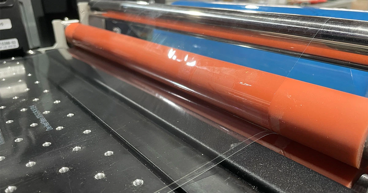
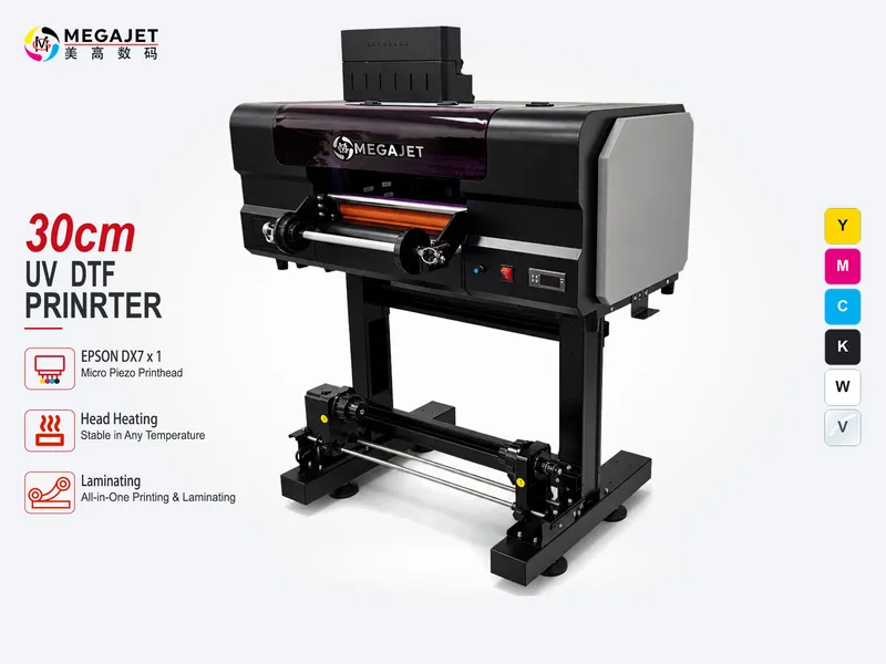
Heated silicone laminating roller and tension bar on a Megajet UV printer.
Table of Contents
In commercial UV DTF (direct-to-film) transfer sticker manufacturing, the printing stage is only half the battle.
Even with an industrial UV flatbed or roll-to-roll printer running genuine Epson i3200-u1 or i1600-u1 printheads delivering crisp micro-detail, poor lamination parameters can instantly ruin an entire gang sheet.
The two most common failure modes reported by overseas print shops and regional distributors are trapped air bubbles (tunneling) and adhesive residue (glue bleed/stringing).
Both defects trace directly back to improper combinations of roller temperature, pneumatic pressure balance, feed tension, and UV varnish cure energy.
This technical guide breaks down the physical and chemical dynamics of AB film lamination, provides factory-tested benchmark settings, and details root-cause solutions for daily workshop operations.
1. The Multi-Layer Physics of AB Film Lamination
To troubleshoot lamination defects, operators must understand the exact composition of the UV DTF composite structure and interface mechanics.
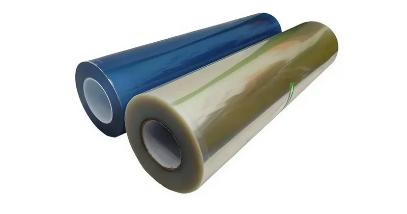
- A-Film (Bottom Carrier Film): A treated PET base coated with a silicone release layer (calibrated to 60–80 g/25mm release force) and a specialized pressure-sensitive adhesive (PSA).
UV white ink, CMYK color ink, and gloss varnish are printed directly onto this adhesive surface.
- Printed Ink & Varnish Stack: UV inks cross-link under 395nm LED lamp irradiation.
The top gloss varnish creates a protective dome and provides a mechanical anchor for the B-film.
- B-Film (Transfer / Positioning Top Film): A protective PET carrier with a high-tack adhesive backing (initial tack ≥ 12 N/25mm) designed to lift the cured ink film off the A-film carrier and transfer it onto the target substrate.
The laminator roller must apply sufficient thermal activation and mechanical pressure to bond the B-film firmly to the raised varnish layer without trapping air or displacing the adhesive boundary.
2. Root Causes and Solutions for Air Bubbles & Tunneling
Trapped air bubbles prevent proper bonding between the B-film and the cured UV graphic, causing parts of the sticker to lift or fail during transfer.
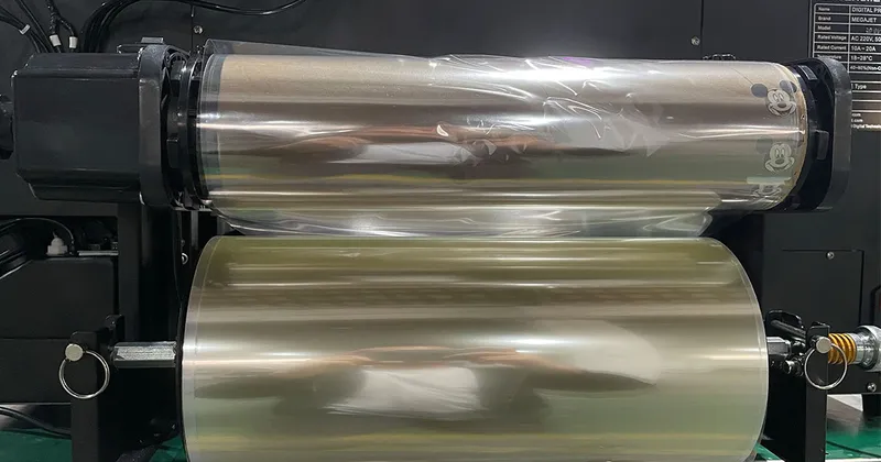
Insufficient or Uneven Roller Pressure
The Mechanism: If the laminating roller lacks mechanical downward force, or if pressure is unequal between the left and right sides of the silicone cylinder, micro-gaps remain along the raised edges of thick UV white ink and embossed varnish passes.
The Fix: Calibrate pneumatic cylinder pressure between 0.25 MPa and 0.35 MPa (2.5 to 3.5 bar) on dual-cylinder regulators, using a 50–60 Shore A silicone roller.
On manual spring-clamp laminators, use a feeler gauge to verify balanced tension across the entire roller width.
Low Lamination Temperature & Dwell Time Physics
The Mechanism: Many generic blogs recommend 40°C–50°C, but this is a critical operational pitfall on commercial roll-to-roll UV DTF printers. In continuous inline production, film moves through the laminator at 1.0–2.0 m/min. The actual contact time (dwell time) under the silicone roller nip is only 0.2–0.3 seconds. Because PET film has low thermal conductivity and ambient airflow continuously cools the roller surface, setting the temperature controller to only 40°C–50°C leaves the effective contact temperature at barely 30°C–35°C. At this low temperature, the PET carrier and PSA adhesive remain rigid and cannot conform smoothly around high-build 3D white ink and embossed gloss varnish passes, creating severe micro-voids and silvering air bubbles.
The Fix: Set the heating roller temperature controller to 80°C (operational window: 75°C–85°C / 167°F–185°F). At standard line speeds, this 80°C setpoint compensates for rapid heat dissipation and delivers an effective dwell temperature of roughly 50°C–60°C to the adhesive interface, softening the PSA just enough to seal perfectly around raised graphics without bubbles.
Tension Mismatch Between Feed and Unwind Shafts
The Mechanism: If the B-film unwind shaft has excessive brake friction while the bottom A-film feeds freely, the top film stretches unevenly, creating longitudinal ripple tunnels (creasing) that trap continuous channels of air.
The Fix: Maintain a synchronized 0.02–0.05N tension differential across the feed and take-up friction dampers.
Both films must enter the roller nip at identical linear speed without slack or excessive drag.
Inadequate or Over-Powered UV Curing
The Mechanism: UV LED lamp calibration cannot be treated with a one-size-fits-all setting because LED lamp wattage and optical irradiance differ significantly across printer models. If curing power is too low, the varnish remains tacky, causing unreacted monomers to outgas post-lamination and create delayed micro-bubbles under the B-film. Conversely, running high-power water-cooled LEDs at excessive intensity (e.g., 80%–100%) overheats and warps the thin PET base film, causing thermal ripples.
The Fix: Calibrate UV lamp output specifically to achieve a dry-to-touch varnish surface without overheating the film. On Megajet commercial printers equipped with high-efficiency LED units, our factory engineers typically set the UV lamp power around 25%–35%, which delivers complete cross-linking while keeping the PET substrate cool and dimensionally stable. Check our detailed guide on UV ink cross-linking and hardness specifications for testing guidelines.
3. Eliminating Glue Residue, Edge Bleed & Adhesive Separation
Glue residue can manifest as sticky adhesive stringing along cut edges, adhesive transfer failure (glue remaining on target items), or messy adhesive squeeze-out during cold storage.
Excessive Roller Temperature (>95°C–100°C) and Hot Standstill Pauses
The Mechanism: Glue bleed does not happen at 80°C under continuous line feeding. Real glue bleed occurs under two conditions: either the operator sets the controller excessively high (exceeding 95°C–100°C / 203°F–212°F), or the printer pauses while the heated roller remains clamped down against stationary film (hot dwell). In these scenarios, prolonged extreme heat causes the pressure-sensitive hot-melt layer to transition into a low-viscosity liquid state. The nip pressure then squeezes melted adhesive outward past the printed graphic contour, leaving sticky edge halos, gumming up cutting blades, and attracting dust.
The Fix: Keep the roller temperature controller at 75°C–85°C (nominally 80°C) during production, and always ensure the pneumatic cylinders raise the heated roller off the film whenever media feeding stops.
Excessive Nip Pressure Squeezing the Glue Bed
- The Mechanism: Extreme downward pneumatic force crushes the adhesive layer, thinning the glue beneath the ink and forming thick ridges of displaced adhesive at graphic boundaries.
During cutting and peeling, this displaced adhesive tears erratically and strings across the substrate.
- The Fix: Maintain cylinder pressure at 0.25–0.35 MPa.
The goal is intimate contact to eliminate air voids, not destructive mechanical compression of the adhesive bed.
Immediate Cutting Without Curing / Resting Time
- The Mechanism: Freshly laminated PSA adhesive requires time for polymer chain relaxation and mechanical leveling across the UV ink topography.
Slitting or gang-cutting sheets immediately after lamination causes wet adhesive shearing along the blade edge.
- The Fix: Implement a mandatory resting window of 30 to 60 minutes (or up to 2 hours in cold weather <18°C) before running laminated rolls through plotters or rotary slitters.
Release Layer Incompatibility
The Mechanism: If the release force between the A-film PET base and its glue is higher than the peel strength of the B-film, the adhesive layer splits internally, leaving sticky residue on the backing sheet or target product.
The Fix: Use factory-matched AB film sets tested under standard ASTM D3359 cross-hatch adhesion protocols to ensure balanced peel ratios.
For more on matching equipment formats, see our analysis on UV DTF roll vs UV flatbed printing setups.
4. Recommended Factory SOP Matrix: Optimal Lamination Parameters
Use the following factory benchmark matrix to calibrate laminator settings across seasonal climate shifts.
| Parameter / Operational Step | Standard Range | Winter / Cold Climate (<18°C) | Summer / Hot Climate (>32°C) |
|---|---|---|---|
| Roller Temperature | 80°C (75°C – 85°C / 167°F – 185°F) | 80°C – 85°C (176°F – 185°F) | 70°C – 75°C (158°F – 167°F) |
| Pneumatic Pressure | 0.25 – 0.35 MPa (2.5–3.5 bar) | 0.30 – 0.40 MPa (3.0–4.0 bar) | 0.20 – 0.28 MPa (2.0–2.8 bar) |
| Lamination Speed | 1.0 – 1.8 m/min | 0.8 – 1.2 m/min | 1.5 – 2.2 m/min |
| UV Lamp Power Output | 25% – 35% (High-power LED; adjust to dry-to-touch) | 30% – 40% (Calibrate to ambient cold) | 20% – 30% (Prevent heat warping) |
| Post-Lamination Rest Time | 30 – 60 minutes | 60 – 120 minutes | 30 minutes |
| Storage Temperature / RH | 20°C–25°C / 45%–60% RH | Warm staging area | Climate-controlled dry room |
5. Daily Operator Troubleshooting Checklist
Before initiating full-shift production runs, verify each item in this 3-stage checklist.
Stage 1: Pre-Print Inspection
Inspect the A-film surface for static dust or handling fingerprints.
Ensure printhead height is calibrated to 1.8mm–2.2mm above the film surface.
Verify that varnish nozzles on the
i3200-u1ori1600-u1printhead are firing 100% clean without deflection.
Stage 2: Inline Lamination Control
Allow the laminator roller to reach its preset temperature and stabilize for at least 10 minutes before feeding film.
Check that the B-film unwind reel does not jerk or stutter during continuous feeding.
Visually verify that the film nip line is perfectly straight across the entire roller length.
Stage 3: Post-Lamination QC Verification
Cut a 10 cm test piece from the leading edge of the batch.
Perform a manual transfer onto a smooth acrylic or glass test piece.
Peel the B-film at a sharp 180° angle: the graphic must transfer cleanly with zero adhesive stringing, zero edge lift, and no glue residue left on the target surface.
Technical Summary & Factory Support
Achieving consistent, zero-defect UV DTF output requires treating lamination as a precision engineering step.
By maintaining roller temperature at 80°C (75°C–85°C) to overcome continuous feed thermal dissipation, setting pneumatic cylinder pressure to 0.25–0.35 MPa, and adhering to strict post-lamination resting intervals, workshops can eliminate over 95% of bubble and glue residue claims.
Whether you are configuring an integrated 2-in-1 hybrid system or running high-speed standalone UV DTF production lines, matching film adhesion characteristics with calibrated thermal rollers is key to maximum production yield.
If your workshop is experiencing persistent adhesive peeling issues or wants to verify parameter profiles for specific substrate applications, send your film and ink specifications to our manufacturing facility or contact the Megajet engineering team to request calibrated SOP profiles and certified AB film test sample packs.